Only a few days left to make it a Christmas gift · Order before Dec 15
Free shipping on orders over $365/€319
14-Day Returns* · 2-Year Warranty · Worldwide Shipping, US Included
Want it under the tree? · Order before Dec 15
Free shipping on orders over $399/€350
14-Day Returns*
2-Year Warranty
Worldwide Shipping, US Included
| Feature | How to Simulate | |------------------------|-----------------------------------------------------| | | Virtual Terminal or COMPIM (with VSPD) | | I2C | I2C Debugger or connect I2C sensor models (e.g., DS1621) | | ADC | Use potentiometer to analog pin → voltage graph | | External Interrupt | Use a button → GPIO → observe in logic analyzer | | PWM (LEDC) | Connect LED + oscilloscope to PWM pin |
Proteus (and indeed most general‑purpose simulators) cannot simulate real‑time wireless communication. The ESP32’s Wi‑Fi and Bluetooth functionality relies on sophisticated RF hardware, protocol stacks, and real‑time scheduling that are far beyond the scope of a behavioural simulator. For any project that depends on wireless features, you must eventually test on physical hardware.
Let's build a foundational testing circuit using an ESP32 and an LED to verify configuration success. Component List LED-RED (Active animation model) RES (330-ohm resistor) GROUND (Found under the Terminals Mode sidebar icon) Circuit Wiring Instructions Place the ESP32 in the center of the schematic sheet.
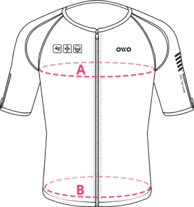
Measure your chest (A) and hips (B) following our indications.
The reference measurement will always be the larger of the two (A or B).
Look in the chart to which size corresponds to that measurement.
| Size | Reference measurements | |
|---|---|---|
| Inches | Centimeters | |
| 2XS | 25.6 – 29.4 | 65 – 74 |
| XS | 29.5 – 32.6 | 75 – 82 |
| S | 32.7 – 36.1 | 83 – 91 |
| M | 36.2 – 39.7 | 92 – 100 |
| L | 39.8 – 42.8 | 101 – 108 |
| XL | 42.9 – 46.3 | 109 – 117 |
| 2XL | 46.4 – 49.9 | 118 – 126 |
| 3XL | 50 – 53 | 127 – 134 |
| 4XL | 53.1 – 55.9 | 135 – 142 |